Makita BHR261 User Manual
Browse online or download User Manual for Rotary hammers Makita BHR261. Repair - Makita
- Page / 24
- Table of contents
- BOOKMARKS
- Optional accessories 1
- ECHNICAL INFORMATION 1
- Features and benefits 2
- Comparison of products 3
- Comparison of products 4
- [2] LUBRICATION 5
- P 5/ 24 5
- Tool holder guide complete 6
- P 7/ 24 7
- P 8/ 24 8
- P 9/ 24 9
- [3] DISASSEMBLY/ ASSEMBLY 10
- P 10/ 24 10
- P 11/ 24 11
- [3] DISASSEMBLY/ASSEMBLY 11
- [3]-3. Change lever 11
- P 12/ 24 12
- [3]-4. Motor section, Switch 12
- P 13/ 24 13
- P 14/ 24 14
- P 15/ 24 15
- P 16/ 24 16
- P 17/ 24 17
- P 18/ 24 18
- Swash bearing portion 19
- P 20/ 24 20
- Circuit diagram 22
- Wiring diagram 23
Summary of Contents
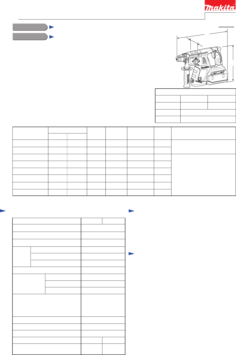
Max. Output(W)BatteryVoltage: VCell and CapacityCapacity : mm ( " )Charging Time: min.5000 - 1,200BHR261 BHR261T0 - 4,80036Li-ion 2.6 AhY
ChangecoverChange ring[3] DISASSEMBLY/ ASSEMBLY[3] -2. Drill chuck assembly for BHR261T (cont.) ASSEMBLINGChuckholderChuck holderShort leg ofTorsion s
P 11/ 24Repair[3] DISASSEMBLY/ASSEMBLY[3]-3. Change leverWhile pushing Lock button into Change lever, turn Change lever to Drill mode.While pushing Lo
P 12/ 24Repair[3] DISASSEMBLY/ASSEMBLY[3]-4. Motor section, SwitchRemove two Pins 6 and two 4x18 Tapping screwsthen separate Handle set (R) from Handl
P 13/ 24Repair[3] DISASSEMBLY/ASSEMBLY[3]-4. Motor section, Switch (cont.)Remove two 4x18 Tapping screws and Brush holder on the front side.Remove an
P 14/ 24Repair[3] DISASSEMBLY/ASSEMBLY[3]-4. Motor section, Switch (cont.)When inserting Armature to Inner housing complete,do not fail to pass Armatu
P 15/ 24Repair[3] DISASSEMBLY/ASSEMBLY[3]-5. Tool holder section (BHR261)/ Tool holder guide section (BHR261T)DISASSEMBLINGInner housingcompleteFlat w
P 16/ 24Repair[3] DISASSEMBLY/ASSEMBLY[3]-6. Needle bearing complete and Oil seal 25DISASSEMBLINGFig. 34Fig. 37ASSEMBLING1) Assemble Oil seal 25 to Ge
P 17/ 24Repair[3] DISASSEMBLY/ASSEMBLY[3]-7. Impact bolt in Tool holder complete (BHR261)/ Tool holder guide complete (BHR261T)DISASSEMBLING(1) When S
P 18/ 24Repair[3] DISASSEMBLY/ASSEMBLY[3]-7. Impact bolt in Tool holder complete (BHR261)/ Tool holder guide complete (BHR261T)(cont.)ASSEMBLINGFig. 4
P 19/ 24Repair[3] DISASSEMBLY/ASSEMBLY[3]-8. Swash bearing 10, Gear portionsDISASSEMBLINGFig. 45Note: The subject step can be done without removing Mo
P 2/ 24One touch slide chuckfor SDS-plus bitElastomer for front guardHigh efficiencyVibration absorbing HandleThe ergonomic design helps pushingaction
P 20/ 24Repair[3] DISASSEMBLY/ASSEMBLY[3]-8. Swash bering 10, Gear portionsDISASSEMBLINGFig. 52 Fig. 53Guide plateNote: Be sure to apply Makita grease
RepairP 21/ 24[4] Maintenance programReplacing the following parts at the same time is recommended when replacing Carbon brushes is required. See Fig.
Circuit diagramP 22/ 24Color index of lead wires' sheathBlackTerminailLEDBrush holdercompleteSwitchWhiteRedFig. D-1
Wiring diagramP 23/ 24Fig. D-2To Brush holdercompleteConnectorConnectorRibsDiodeSwitchRoute Lead wires betweenRib and Inner wall of Housing.Route Lead
Wiring diagramP 24/ 24RibLead wire (yellow) between Terminal and ConnectorTerminalTubeConnectorLead wrie (black)YokeConnectorPut Connectorinto the spa
P 3/ 24Model No.Makita BOSCH HILTITE7-ADEWALT HitachiDH36DAL/ DL0 - 550 / 0 - 1,1000 - 2,250 / 0 - 4,50018.812.492.5YesNoNoYesYes / No4.0 (8.8) / 3.9
Comparison of productsP 4/ 24Numbers in charts below are relative values when the capacity of Model GBH36V-LI is indexed at 100.Note: The test resul
[2] LUBRICATION[1] NECESSARY REPAIRING TOOLSRepairDescriptionCode No. Use forRetaining ring S pliers ST-2N1R003Removing Ring spring 19 from Tool holde
Gear section: 17gCrank section: 5gSwash bearing section: 4g(Refer to Fig. 1.)Emboss forfixing Compressionspring 14Inside view of Inner housing[2] LUBR
[3] DISASSEMBLY/ASSEMBLY[3] -1. Bit holder section for BHR261/ Holder section for Drill chuck of BHR261TDISASSEMBLING for BHR261DISASSEMBLING for BHR2
[3] DISASSEMBLY/ASSEMBLY[3] -1. Bit holder section for BHR261/ Holder section for Drill chuck of BHR261T (cont.) ASSEMBLING for BHR261TaNote: Face the
[3] DISASSEMBLY/ ASSEMBLY[3] -2. Drill chuck assembly for BHR261TDISASSEMBLINGFig. 10 Fig. 11Fig. 14Fig. 13Fig. 12Steel ball 5.0Leaf springFlat washer
More documents for Rotary hammers Makita BHR261


Related products and manuals for Rotary hammers Makita BHR261


 (48 pages)
 (40 pages)
 (16 pages)
(32 pages)
(16 pages)
(18 pages)
(16 pages)
(32 pages)
(16 pages)
(18 pages)
© 2020, manymanuals.com. All rights reserved. | 0.347 s |
 Manymanuals.com
 Manymanuals.de
 Manymanuals.fr
 Manymanuals.it
 Manymanuals.pl
 Manymanuals.cz
 Manymanuals.es
 Manymanuals-pt.com
Comments to this Manuals