Makita 3702B User Manual
Browse online or download User Manual for Power tools Makita 3702B. Makita 3702B User's Manual
- Page / 23
- Table of contents
- BOOKMARKS
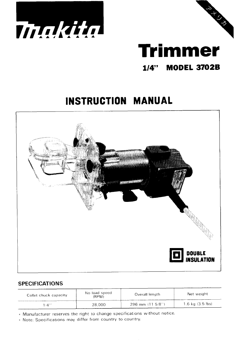
- Tkimmer 1
- SAFETY INSTRUCTIONS 2
- ADDITIONAL SAFETY RULES 4
- THESE INSTRUCTIONS 4
- Trimmer 5
- CAUTION 6
- (1/8") 7
- Straight guide 8
- 3/64" 10
- Templet 11
- (25/64") 12
- MAINTENANCE 13
- ACCESS0 14
- -Single 15
- -I& 16
- CORNER ROUNDING 17
- BEADING 17
- PANEL PILOT 17
- 7" 18
- 22" 19
- -self Piloting 19
- TRIMMER 21
- 'k,'o" 22
- Makita Corporation 23
Summary of Contents
Tkimmer Collet chuck capacity 14 _~____~__ 1/4” MODEL 3702B Net weight Overall lenqth No load speed (RPMI 28 000 296 mm 11 1 5 8 1 1 6 kg 13 5 lbsl -
Trimmer guide Trimming, curved cuts for furniture and the like can be done easily with the trimmer guide. The guide roller rides the curve and
Templet guide The templet guide provides a sleeve through which the bit passes, allowing use of the trimmer with templet patterns. Remove the too
Secure the templet to the workpiece. Place I the tool on the templet and move the tool with the templet guide sliding along the side of the tem
MAINTENANCE CAUTION : Always be sure that the tool is switched off and unplugged before attempting to perform inspection or maintenance. Replacing ca
ACCESS0 R I ES CAUTION : These accessories or attachments are recommended for use with your Makita tool specified in this manual. The use of
Bits STRAIGHT -Single Flute HIGH SPEED STEEL PART NO. A E C D E 733232-6A 118 5/16 1-1 18 114 1-518 CARBIDE TIPPED PART NO @ STRAIGHT - 2 Flute A
ROUND NOSE -I& CARBIDE TIPPED PART NO. A a C D E 733008-4A 318 9/16 1-114 1 I4 2 733008-2A 114 15132 1-1 I4 1 /4 1-718 CORE BOX 4DC &
PANEL PILOT HIGH SPEED STEEL PART NO. A B C D E 733236-0A 114 314 1 114 2-7116 CORNER ROUNDING CARBIDE TIPPED - Ball Bearing Pilot 733120 OA 7/8
ROMAN OGEE CARBIDE TIPPED - Ball Bearing Pilot I PARTNO. AI A? B C 0 E RI 5132 I 733123-2A 1 3/8 15/32 1-1/4 1/4 REPLACEMENT BEARING - NO, 733132
COMB1 NATION F LUSH/2Z0 BEVEL TRIMMER SDC CARBIDE TIPPED 733128-6A 7/16 112 3/16 1-1/4 1/4 1-314 3 FLUTE FLUSH TRIMMER ASSEMBLY -Self Piloting
IMPORTANT SAFETY INSTRUCTIONS (For All Tools) WARNING: WHEN USING ELECTRIC TOOLS, BASIC SAFE- REDUCE THE RISK OF FIRE, ELECTRIC SHOCK, AND PER-
3 FLUTE 22" BEVEL REPLACEMENT CUTTER LA4 SOLID CARBIDE I PARTNO. A B D I 733129-8A 718 3/8 1 /4 FOR BEVEL TRIMMER ASSEMBLY NO, 733129-4A 114
Apr 06 ‘89 US 114” TRIMMER Model 3702B Note The switch, noise suppressor and other part conflguratlons may differ from country to country
MODEL 37028 ;:, DESCRIPTION Apr 04 '89 US 'k,'o" ,"., DESCRIPTION MACHINE ~ 1 2 3 4 6 7 8 9 10 11 12 13 14 15 16 17 18 19 2
MAKITA LIMITED ONE YEAR WARRANTY Warranty Policy Every Makita tool IS thoroughly inspected and tested before leaving the factory. It IS warranted t
14. REMOVE ADJUSTING KEYS AND WRENCHES. Form habit of checking to see that keys and adjusting wrenches are removed from tool before turning it on. 15
ADDITIONAL SAFETY RULES 1. Wear hearing protection during extended periods of operation. 2. Handle the bits very carefully. 3. Check the bit careful
Installing or removing trimmer bit CAUTION : Always be sure that the tool is switched off and unplugged before installing or removing the bit. In
Adjusting angle of tool base Loosen the wing bolts and adjust the angle of the tool base (5' per graduation) to obtain the desired cutting an
When doing edge cutting, the workpiece surface should be on the left side of the bit in the feed direction. (See the figure below) Feed directio
Straight guide The straight guide is effectively used for straight cuts when chamfering or grooving. Attach the guide plate to the straight guide
Circular work 0Circular work may be accomplished if you assemble the straight guide and guide plate 0 Min. and max. radius of circles to be cut
Related products and manuals for Power tools Makita 3702B


 (48 pages)

 (28 pages)
(16 pages)
(16 pages)
(6 pages)
(14 pages)
(8 pages)
(12 pages)
(8 pages)
(28 pages)
(24 pages)
(20 pages)
(20 pages)
(20 pages)
(20 pages)
(24 pages)
(20 pages)
(2 pages)
(20 pages)
(20 pages)
(28 pages)
(16 pages)
(16 pages)
(6 pages)
(14 pages)
(8 pages)
(12 pages)
(8 pages)
(28 pages)
(24 pages)
(20 pages)
(20 pages)
(20 pages)
(20 pages)
(24 pages)
(20 pages)
(2 pages)
(20 pages)
(20 pages)
© 2020, manymanuals.com. All rights reserved. | 2.220 s |
 Manymanuals.com
 Manymanuals.de
 Manymanuals.fr
 Manymanuals.it
 Manymanuals.pl
 Manymanuals.cz
 Manymanuals.es
 Manymanuals-pt.com
Comments to this Manuals